Difference between revisions of "Directions to build the 555 tone generator"
From MakeICT Wiki
Jump to navigationJump to search| Line 1: | Line 1: | ||
| − | '''List of materials: | + | '''List of materials:''' |
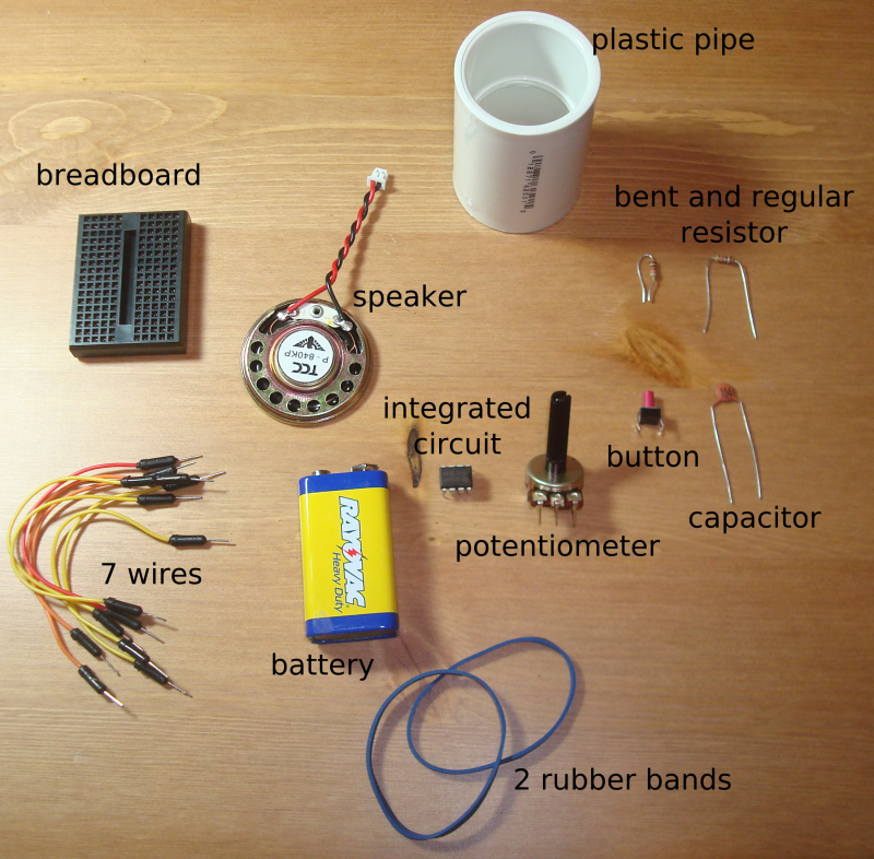
[[File:555ListOfParts.png|caption|none|800px]] | [[File:555ListOfParts.png|caption|none|800px]] | ||
| Line 15: | Line 15: | ||
* 2 rubber bands | * 2 rubber bands | ||
| − | + | # Confirm that you have all the parts. | |
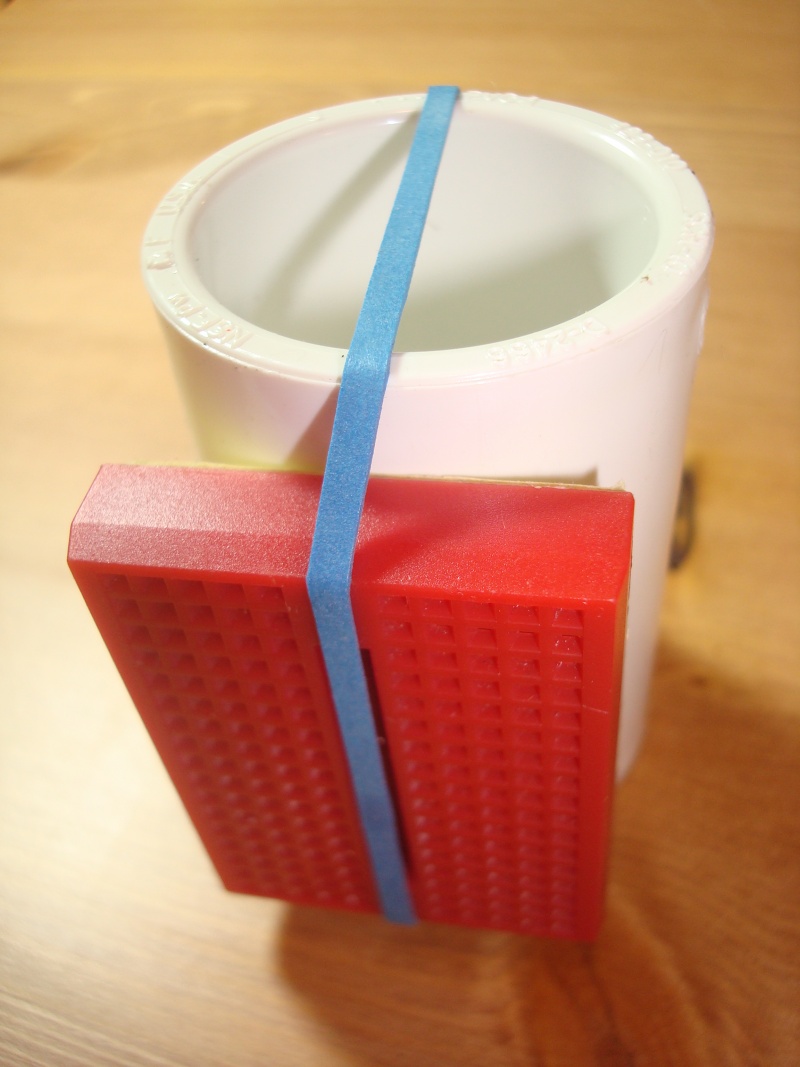
| − | + | [[File:rubberBandAroundPipe.jpg|caption|none|800px]] | |
| − | + | # Put a rubber band around the plastic pipe. Take care to center the rubber band. Put the breadboard under the rubber band. | |
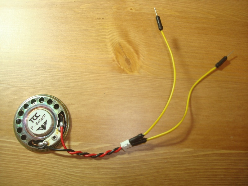
| − | + | [[File:wireToSpeakerPlug.jpg|caption|none|800px]] | |
| − | + | # Put one wire in each hole on the white plastic end of the speaker wire. | |
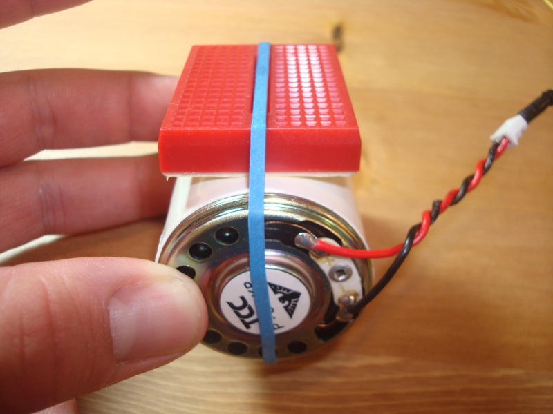
| − | + | [[File:speakerToTube.jpg|caption|none|800px]] | |
| − | + | # Put the speaker on the end of the plastic tube (under the rubber band). Make sure the wires come out of the right side of the rubber band. | |
| − | + | [[File:attachPot.jpg|caption|none|800px]] | |
| − | + | # Carefully insert the potentiometer into the back left of the breadboard (every other hole). Make sure the legs of the potentiometer are straight before trying this. | |
| − | + | [[File:attachBattery.jpg|caption|none|800px]] | |
| − | + | # Put the battery on the right side of the breadboard, and put the second rubber band around the plastic tube. Line the rubber band up with the edge of the potentiometer. | |
| − | + | [[File:insertIC.jpg|caption|none|800px]] | |
| − | + | # Across the middle of the breadboard, put the integrated circuit in the sixth hole from the front. Make sure the notch on the chip points toward the speaker. | |
| − | + | [[File:insertCap.jpg|caption|none|800px]] | |
| − | + | # Put the capacitor from the third hole on the left of the integrated circuit to the front hole on the right of the integrated circuit. | |
| − | + | [[File:insertBentResistor.jpg|caption|none|800px]] | |
| − | + | # Put the bent resistor in the first two holes next to the left side of the integrated chip. Skip a hole between the integrated chip and the resistor. | |
| − | + | [[File:insertregResistor.jpg|caption|none|800px]] | |
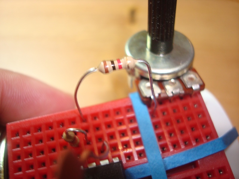
| + | # Put the regular resistor in the seventh hole on the left side of the board. Put the other end in the first hole next to the potentiometer. | ||
| + | [[File:insertButton.jpg|caption|none|800px]] | ||
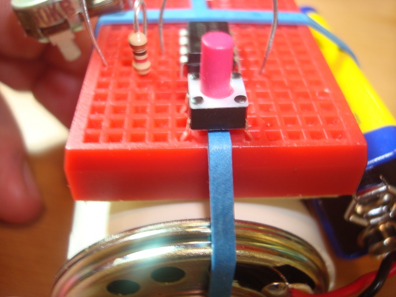
| + | # Put the button in the first holes across the center of the breadboard. Make sure the switch is turned the right way (see picture). | ||
| + | [[File:insertWire1.jpg|caption|none|800px]] | ||
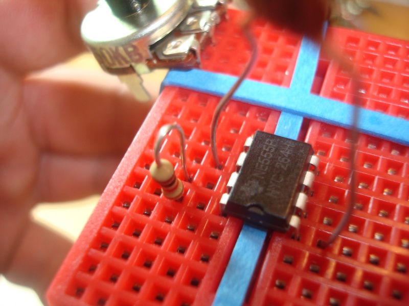
| + | # Put a wire from the right side second hole of the integrated circuit to the left side third hole of the integrated circuit (next to the capacitor). | ||
| + | [[File:insertWire2.jpg|caption|none|800px]] | ||
| + | # Put a wire from the right side last hole of the integrated circuit to the left side first hole of the integrated circuit. | ||
| + | [[File:insertWire3.jpg|caption|none|800px]] | ||
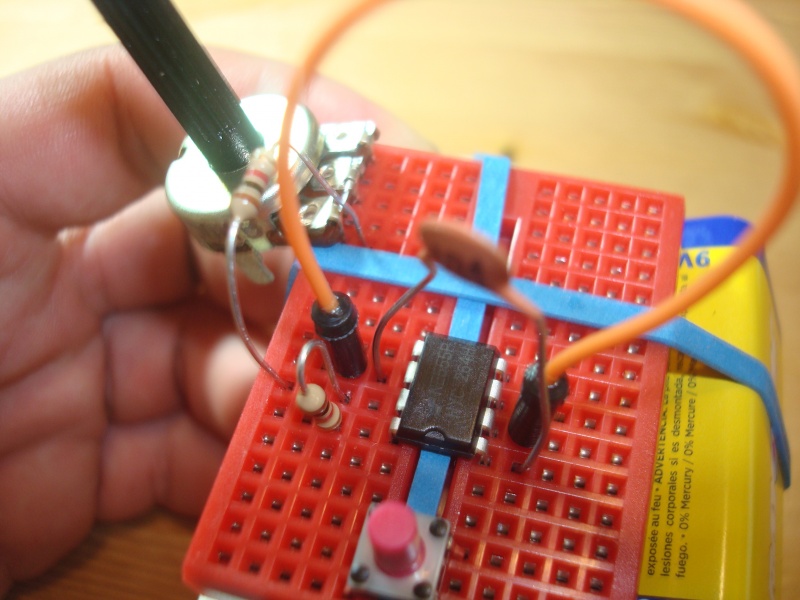
| + | # Put a wire from the third to the last hole next to the potentiometer to the third hole on the left of the integrated circuit (next to the capacitor and wire). | ||
| + | [[File:insertWire4.jpg|caption|none|800px]] | ||
| + | # Put a wire from the third hole on the front left of the breadboard to the sixth hole on the front left of the breadboard. | ||
| + | [[File:insertWire5.jpg|caption|none|800px]] | ||
| + | # Put a wire from the second hole in the second row from the front right of the board to the sixth hole on the right side of the board. | ||
| + | [[File:attachSpeakerWires.jpg|caption|none|800px]] | ||
| + | # Put one of the speaker wires in the third hole on the right of the breadboard and the other in the eighth hole on the right of the breadboard. | ||
| − | + | ''You're almost done! Get someone to make sure your circuit is right so you can turn it on!'' | |
Revision as of 01:23, 24 February 2014
List of materials:
- 1 breadboard
- 1 speaker
- 1 plastic pipe
- 1 bent resistor
- 1 regular resistor
- 1 capacitor
- 1 button
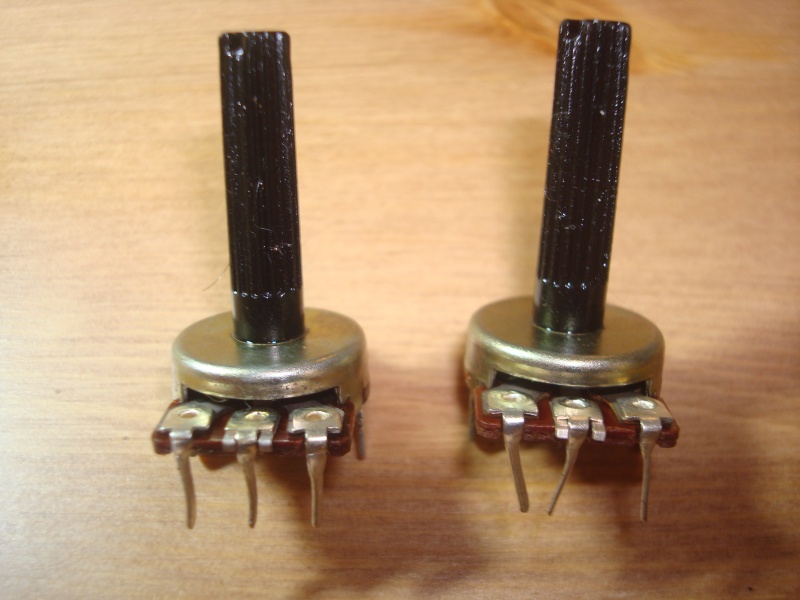
- 1 potentiometer
- 1 integrated circuit
- 1 battery
- 7 wires
- 2 rubber bands
- Confirm that you have all the parts.
- Put a rubber band around the plastic pipe. Take care to center the rubber band. Put the breadboard under the rubber band.
- Put one wire in each hole on the white plastic end of the speaker wire.
- Put the speaker on the end of the plastic tube (under the rubber band). Make sure the wires come out of the right side of the rubber band.
- Carefully insert the potentiometer into the back left of the breadboard (every other hole). Make sure the legs of the potentiometer are straight before trying this.
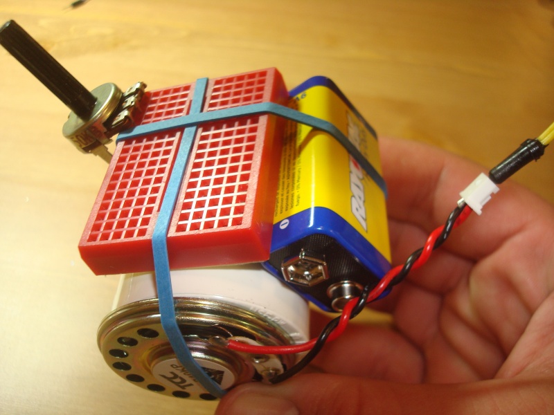
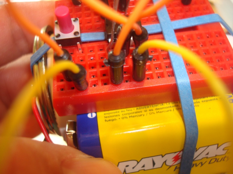
- Put the battery on the right side of the breadboard, and put the second rubber band around the plastic tube. Line the rubber band up with the edge of the potentiometer.
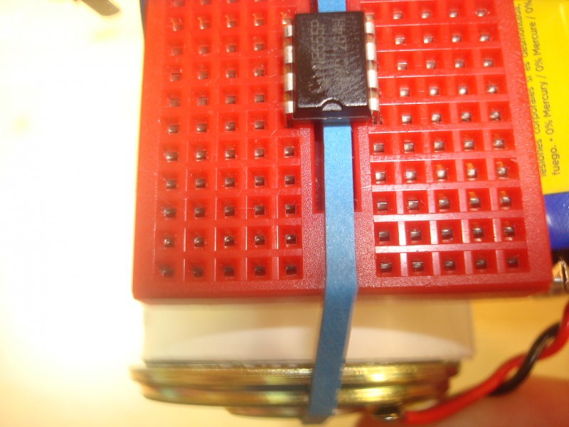
- Across the middle of the breadboard, put the integrated circuit in the sixth hole from the front. Make sure the notch on the chip points toward the speaker.
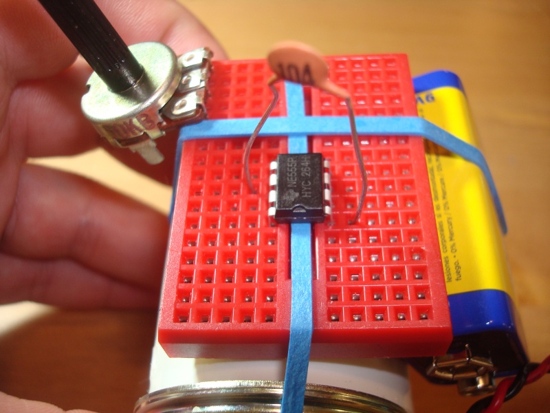
- Put the capacitor from the third hole on the left of the integrated circuit to the front hole on the right of the integrated circuit.
- Put the bent resistor in the first two holes next to the left side of the integrated chip. Skip a hole between the integrated chip and the resistor.
- Put the regular resistor in the seventh hole on the left side of the board. Put the other end in the first hole next to the potentiometer.
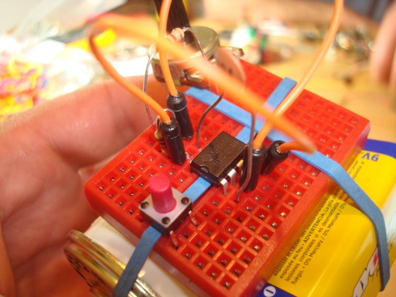
- Put the button in the first holes across the center of the breadboard. Make sure the switch is turned the right way (see picture).
- Put a wire from the right side second hole of the integrated circuit to the left side third hole of the integrated circuit (next to the capacitor).
- Put a wire from the right side last hole of the integrated circuit to the left side first hole of the integrated circuit.
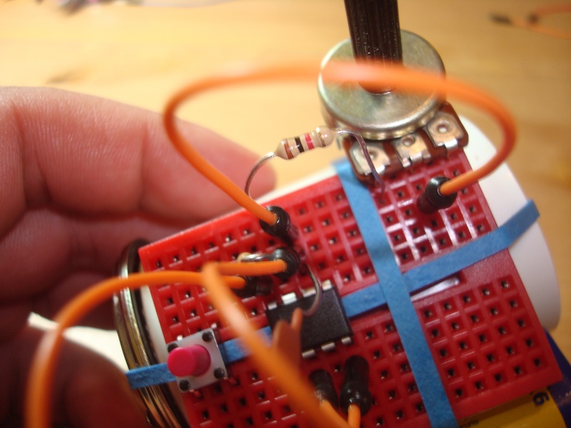
- Put a wire from the third to the last hole next to the potentiometer to the third hole on the left of the integrated circuit (next to the capacitor and wire).
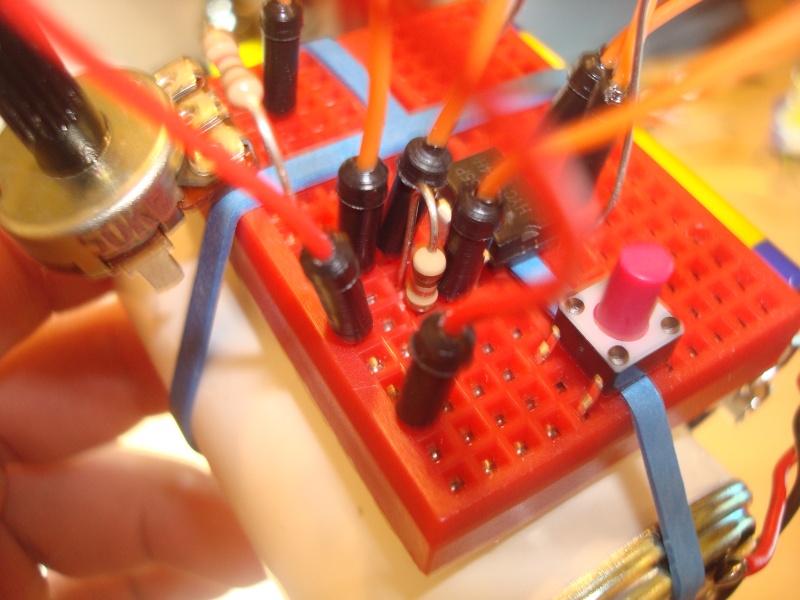
- Put a wire from the third hole on the front left of the breadboard to the sixth hole on the front left of the breadboard.
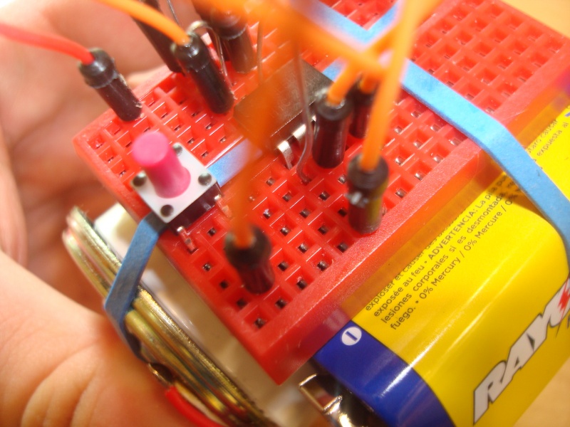
- Put a wire from the second hole in the second row from the front right of the board to the sixth hole on the right side of the board.
- Put one of the speaker wires in the third hole on the right of the breadboard and the other in the eighth hole on the right of the breadboard.
You're almost done! Get someone to make sure your circuit is right so you can turn it on!
