Difference between revisions of "CNC Plasma Cutter"
Steve Owens (talk | contribs) |
Kim Kirwan (talk | contribs) (Added "Introduction" and "Safety", many minor edits) |
||
| (40 intermediate revisions by 5 users not shown) | |||
| Line 1: | Line 1: | ||
| − | == | + | <br />[[File:Cnc plasma table.jpg|thumb]] |
| + | ==Introduction== | ||
| + | [[File:Cnc plasma table.jpg|thumb]]MakeICT's CNC Plasma Cutter is composed of a [https://www.hypertherm.com/ Hypertherm] "Powermax 85" power supply with a compatible 180 degree (straight, machine-held) plasma torch, as well as a MakeICT-built 3-axis/4-motor plasma table with a motion-control system based on [https://linuxcnc.org/ LinuxCNC]. Any CAD/CAM (or hand) method of generating a cut path in g-code that is acceptable to LinuxCNC can be used. Also, for simple parts the LinuxCNC system can do conversational programming (one step at a time) interactively without using CAD/CAM programming. | ||
| − | + | ==Safety== | |
| + | Like any powerful and useful tool, a CNC plasma cutter presents some dangers: | ||
| − | * | + | *A plasma arc, like a welding arc, is very bright and rich in ultraviolet light, do not look at it without suitable eye protection. |
| − | * | + | *A plasma cutter creates a lot of debris and residue, and although the majority of it goes into the table and is caught, the remainder is thrown in all directions as bits of hot metal. Wear protective clothing and shoes so that sparks and hot metal will not burn your feet, legs, arms, etc. |
| − | * | + | *A plasma cutter creates a lot of smoke and fine dust, open a window and use the ceiling exhaust/vent fanto relieve this problem. The small floor fan can be a big assist too. |
| − | * | + | *The plasma arc is generated using high voltages and currents, keep fingers away from the torch tip while it is operating (i.e., do not reach in to try to fix tip-ups). |
| − | * | + | *MakeICT's CNC Plasma Cutter is able to help you see what will happen before making an actual cut, by "framing" your job and by making dry runs, repositioning as needed, with the torch off until you are sure. You don't have to turn the torch on until you're ready. |
| + | *The torch can move very quickly, and sometimes in surprising directions, keep your hands away from all themoving parts (and pinch points) while it is running. | ||
| + | *After the plasma cutting is finished, the workpiece(s) and scrap will be very hot. No, I mean '''very''' hot. For a ''long time'' very hot. Please be careful. | ||
| − | The | + | ==Consumables== |
| + | |||
| + | The main consumables (for the plasma torch tip) that a member will probably need to buy are: | ||
| + | |||
| + | *Electrode - 220842 | ||
| + | *45A Tip - 220941 | ||
| + | *65A Tip - 220819 | ||
| + | *45A/65A Shield - 220798 (the 220818 drag tip would be used if you were cutting by hand) | ||
| + | *45A FineCut Tip - 220930 | ||
| + | *FineCut Shield - 220948 (the FineCut tip needs a different shield) | ||
| + | |||
| + | You must provide your own electrodes and tips. There is currently a FineCut shield on the plasma cutter, but you may need to provide your own 45A/65A shield. | ||
[[File:Plamas consumables.png]] | [[File:Plamas consumables.png]] | ||
[[File:Plamas nossle part numbers.png]] | [[File:Plamas nossle part numbers.png]] | ||
| − | == 65 Specs == | + | ==65 Specs== |
[[File:Plamsa 65A mild steel.png]] | [[File:Plamsa 65A mild steel.png]] | ||
| Line 20: | Line 36: | ||
[[File:Plamsa 65A aluminum.png]] | [[File:Plamsa 65A aluminum.png]] | ||
| − | == 45 Specs == | + | ==45 Specs== |
[[File:Plamas 45 mild steel.png]] | [[File:Plamas 45 mild steel.png]] | ||
| Line 26: | Line 42: | ||
[[File:Plamsa 45 aluminum.png]] | [[File:Plamsa 45 aluminum.png]] | ||
| − | == Finecut Specs == | + | ==Finecut Specs== |
[[File:Plamas finecut mild steel.png]] | [[File:Plamas finecut mild steel.png]] | ||
[[File:Plamas finecut stainless steel.png]] | [[File:Plamas finecut stainless steel.png]] | ||
| − | == Fusion 360 == | + | ==Fusion 360== |
| − | + | '''HOW-TO VIDEO''': [https://www.youtube.com/watch?v=PqFORw6VmNU MakeICT Plasma Setup in Fusion 360 (video)] | |
| + | '''HOW-TO VIDEO''': [https://www.youtube.com/watch?v=ySTToqZ7S7o CNC Plasma First Part in Fusion 360 (video)] | ||
| − | |||
| + | Fusion 360 can be used to easily generate the G-code for our CNC Plasma Cutter. The following is some useful information that can get you started. To learn more you can check the [http://help.autodesk.com/view/fusion360/ENU/?guid=GUID-C14B9F20-3A39-4930-971E-BDFE268384B9 2D Profile reference] for an explanation of each of the 2D profile settings. | ||
| − | |||
| − | |||
| + | To get started with default settings that work with MakeICT's plasma table, download the following files. | ||
| − | |||
| − | |||
| − | |||
| + | '''POST PROCESSOR''' | ||
| + | |||
| + | The first thing you want to do is to grab the Post-Processor. This will ensure that your G-Code matches what our table needs to operate. This really just replaces the M3 with a pierce probe and adds an M5 to stop the torch. | ||
| + | |||
| + | *[https://drive.google.com/file/d/1Q4T7HNoS423AGpF3RqtHjXEXta4RsMse/view?usp=share_link Post-Processor] | ||
| + | |||
| + | |||
| + | '''TEMPLATES''' | ||
| + | |||
| + | You also want to grab the templates for our table. This is not required, but it will save you from having to track down all of the tool settings yourself. | ||
| + | |||
| + | *[https://drive.google.com/open?id=1Zl0KW_o20BaD3otW77eSzxf5Uu55JEyH .125 LeadIn with Kerf] | ||
| + | *[https://drive.google.com/open?id=14-KvUMwOmsKKnDHA1Sk77yUqEtM6Mj4y No LeadIn or Kerf] | ||
| + | |||
| + | If you do change the tool settings and the dimensions of your cut parts are important, using ‘Compensation Type: In computer’ under the ‘Passes’ tab is recommended for best accuracy. Using ‘Compensation Type: In control’ will cause errors in LinuxCNC without manual editing of the g-code, and will give inconsistent results. | ||
| + | |||
| + | '''TOOLS''' | ||
Finally grab the tool files. | Finally grab the tool files. | ||
| − | |||
| − | |||
| − | |||
| + | *[https://drive.google.com/open?id=1qDB9Xsch6fngfBSZE5DU2Ulljm6nY5ZF 45 Amp Tip] | ||
| + | *[https://drive.google.com/open?id=1bX023Ehqh-aDlCkZeNsPDFm2ktYIDt4- 65 Amp Tip] | ||
| + | *[https://drive.google.com/open?id=1fyAXXyNl0gN45t1EUx54SfqRpDQA_9JW Fine Cut Tip] | ||
| + | |||
| + | |||
| + | Once you have the files all downloaded you will need to upload them to your Fusion 360 account. You only need to do this once, unless the files change and you need to replace them. | ||
| + | |||
| + | Open Fusion 360 | ||
| + | |||
| + | *Go to the upper right corner ... you should see your name | ||
| + | *Click on your name and select "Preferences" | ||
| + | *Under "General" ... select "Manufacture" | ||
| + | *Check the "Enable Cloud Libraries" checkbox and click the OK button. | ||
| + | *On the main window, click on the "Show Data Panel" icon in the upper left hand corner (looks like a 3x3 box grid). | ||
| + | *On the left side of the window, you should see a tab that shows "Projects, Libraries, and Samples". If you do not see this, then at the top you should see a big bold < symbol. Click this, and it should take you to the right place. | ||
| + | *Under Libraries click on Assets | ||
| + | *You should now see 4 folders ... CAMMachines, CAMPosts, CAMTemplates, CAMTools | ||
| + | |||
| + | * CAMPosts - 1 Post Processor File | ||
| + | * CAMTemplates - 2 Template Files | ||
| + | * CAMTools - 3 Tool Files | ||
| + | |||
| + | *Click on the folder that you want to upload, and then drag the file(s) from your download folder to the dialog, and click the Upload Button. | ||
| + | *Repeat for each folder. To switch to a new folder, you can either click the < at the top and then click on the Assets folder again. Or, on the far left, you should see the folder you are working on (a triangle symbol followed by > followed by the Folder Name). Click on the triangle, and it will show you all of the folders. If you click on the > symbol, it will give you a drop down with all of the folders. | ||
| + | |||
| + | Now you are ready to begin using Fusion 360 to design your job. | ||
| + | |||
| + | Some basic steps: | ||
| + | |||
| + | '''Create Sketch''' | ||
| + | |||
| + | *Start a new Model | ||
| + | *Select the X/Y plane (red/green) | ||
| + | *Create a new sketch | ||
| + | *Insert an image or SVG ... or you can draw your sketch by hand. | ||
| + | *Make sure you have extruded your drawing (especially if you are using an image or SVGlong time). The depth does not matter, it just has to be extruded. | ||
| + | |||
| + | |||
| + | '''Switch to MANUFACTURE mode''' | ||
| + | |||
| + | *Add a new setup | ||
| + | *Select "Cutting" operation. | ||
| + | *Click on the bottom left corner of your drawing to select the anchor point. | ||
| + | *Right click on the setup you just created, and select "Create From Template". | ||
| + | *You should have two templates that you added earlier. Use the "MakeICT no leadin or Kerf" for the cases where a quick generation time and getting every pierce is required. The "MakeICT .125 lead in with Kerf" is recommended for dimensional parts but suffer from slower generation time and instability if multiple holes are smaller than .125in. | ||
| + | *You should now have a new tool showing ... it will have a red circle with an exclamation mark. If you don't see this, click the little triangle to the left of the setup. | ||
| + | *Right click on the new tool, and select edit. | ||
| + | *Click on Tool and select the tip size that you will be using for cutting. This should be on the left side under the Cloud section. | ||
| + | *Select the correct material size. | ||
| + | *Switch to Geometry, select the area to cut. | ||
| + | *If you have small parts that may fall into the water, you can add tabs at desired points. Typically you just want one tab per item, to make it easier to remove in the end. | ||
| + | *Click OK to close the edit dialog. | ||
| + | *You should now see the tool path on the drawing. You can right click on the setup to simulate the operation if you want to see how it will cut. | ||
| + | *Final step is to apply the Post-Processor. This will generate the G-Code that you will load on the plasma cutter. Right click on the setup and select Post Process. | ||
| + | *Make sure that the "Configuration Folder" says <My Cloud Posts>. If it doesn't, click the Setup Button, an switch it to Cloud | ||
| + | *You should only have one option, but make sure that the Post Configuration section has the MakeICT plasma processor selected. | ||
| + | *At the bottom Left, change the Units to Inches. | ||
| + | *Change the Output Folder to the location you want to save your G-Code. You will need this on a USB flash drive, to put it on the plasma computer. | ||
| + | |||
| + | |||
| + | '''Ready to move to the Plasma''' | ||
| + | |||
| + | <br /> | ||
| + | |||
| + | =Sheetcam= | ||
| + | |||
| + | #Open Sheetcam in windows or Linux. | ||
| + | #Click File - New part - Click yes if prompted. | ||
| + | #Choose file you wish to add .svg or .dxf. | ||
| + | #Part should be loaded into Sheetcam. | ||
| + | #Change X & Y coordinates to .15 at the bottom of the screen. | ||
| + | #Click operation - Plasma Cut. | ||
| + | #Choose correct tool & layer. | ||
| + | #Check for lead-ins and lead-in length - Click ok. | ||
| + | #Look at true width by clicking. | ||
| + | #Check starting points. | ||
| + | #Click Edit start points if they need to be modified. | ||
| + | #If everything looks good, click run post processor | ||
| + | #Title accordingly and save as .ngc | ||
| + | |||
| + | <br /> | ||
| + | =LinuxCNC= | ||
| + | |||
| + | *Notes: At this time the THC (Torch Height Control) and the Ohmic Touchoff are not wired up. Make sure they are not selected. Will post here when that changes, along with a tutorial on using them. | ||
| + | |||
| + | *Turn on Computer & Table power. | ||
| + | *DO NOT TURN ON PLASMA CUTTER YET! | ||
| + | *Log in to PC | ||
| + | **User Name: plasma | ||
| + | **Password: linuxcnc | ||
| + | *Start LinuxCNC from the icon on the desktop. | ||
| + | *Click "Power" button (top middle of the screen). If the "Power" button is disabled/greyed out, make sure the E-stop is not pressed. | ||
| + | *Click the "Home All" button in the lower right. | ||
| + | *[[File:HomeAll.png]] | ||
| + | * | ||
| + | *Move the machine with the arrow keys on the keyboard or with the GUI to the material, and position it according to your Fusion 360 setup file. (e.g. for most files, this is the lower left portion of the material) | ||
| + | *Click "open touch off" button - - Note: only the X and Y need to be touched off. | ||
| + | *[[File:Touchoff.png]] | ||
| + | *Click the file button to select your file | ||
| + | *[[File:File Button.png]] | ||
| + | *Choose the correct .ngc file. | ||
| + | *Double check size measurements on screen to material size.. | ||
| + | *Dry Run with Torch Off by making sure the torch button is not checked. | ||
| + | *[[File:Torch Button.png]] | ||
| + | *If everything looks correct, you are ready to test run the program via the Cycle Start button. | ||
| + | *[[File:Cycle Start.png]] | ||
| + | *Press the Cycle Start button and have your hand over the escape key on the keyboard or on the E-Stop. | ||
| + | *If Dry Run goes well you can now turn on the Plasma Cutter via clicking the torch button. | ||
| + | *Set Amperage accordingly on the front of the machine to the nozzle selected and how it was programmed. | ||
| + | *Make sure the compressor is on and the valve is open. | ||
| + | *Before cutting, make sure the welding curtains are closed and everyone has proper eye protection. (Shade 5 or above) | ||
| + | *Treat the torch as if it could turn on at any time. | ||
| + | *Do not put your hand under the torch unless the Plasma Cutter is off. | ||
| + | *You can now press the Cycle Start button while still hovering over the escape key or E-Stop. | ||
| + | *Let the program finish & remove your part or parts. | ||
| + | |||
| + | <br /> | ||
| + | =Clean up= | ||
| + | |||
| + | #Use rags to clean off any water that may be on the machine | ||
| + | #Wipe rails and torch shield off with rags. | ||
| + | #Sweep the floor and pick up any trash. | ||
| + | <br /> | ||
| + | =Shutdown= | ||
| − | + | #When finished Shut off the Plasma cutter first! | |
| + | #Then shut off the table power and shut down the PC. | ||
| + | #Shut off Compressor and clean up any messes you have made. | ||
| − | + | {{todo|what=Add instructions for setting up sheetcam post processor on personal equipment.}} | |
| − | |||
| − | |||
| − | |||
| − | |||
| − | |||
| − | |||
Latest revision as of 01:26, 23 February 2025
Contents
Introduction
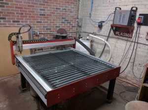
MakeICT's CNC Plasma Cutter is composed of a Hypertherm "Powermax 85" power supply with a compatible 180 degree (straight, machine-held) plasma torch, as well as a MakeICT-built 3-axis/4-motor plasma table with a motion-control system based on LinuxCNC. Any CAD/CAM (or hand) method of generating a cut path in g-code that is acceptable to LinuxCNC can be used. Also, for simple parts the LinuxCNC system can do conversational programming (one step at a time) interactively without using CAD/CAM programming.
Safety
Like any powerful and useful tool, a CNC plasma cutter presents some dangers:
- A plasma arc, like a welding arc, is very bright and rich in ultraviolet light, do not look at it without suitable eye protection.
- A plasma cutter creates a lot of debris and residue, and although the majority of it goes into the table and is caught, the remainder is thrown in all directions as bits of hot metal. Wear protective clothing and shoes so that sparks and hot metal will not burn your feet, legs, arms, etc.
- A plasma cutter creates a lot of smoke and fine dust, open a window and use the ceiling exhaust/vent fanto relieve this problem. The small floor fan can be a big assist too.
- The plasma arc is generated using high voltages and currents, keep fingers away from the torch tip while it is operating (i.e., do not reach in to try to fix tip-ups).
- MakeICT's CNC Plasma Cutter is able to help you see what will happen before making an actual cut, by "framing" your job and by making dry runs, repositioning as needed, with the torch off until you are sure. You don't have to turn the torch on until you're ready.
- The torch can move very quickly, and sometimes in surprising directions, keep your hands away from all themoving parts (and pinch points) while it is running.
- After the plasma cutting is finished, the workpiece(s) and scrap will be very hot. No, I mean very hot. For a long time very hot. Please be careful.
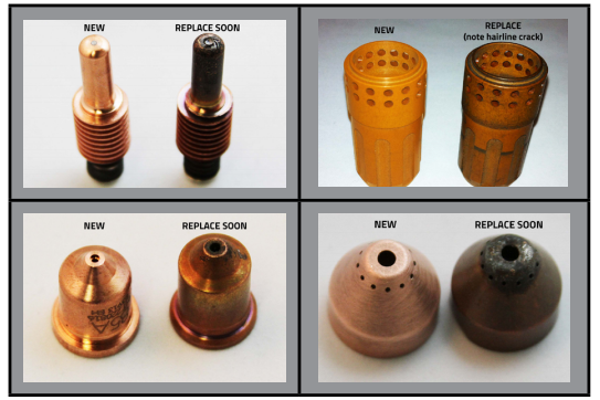
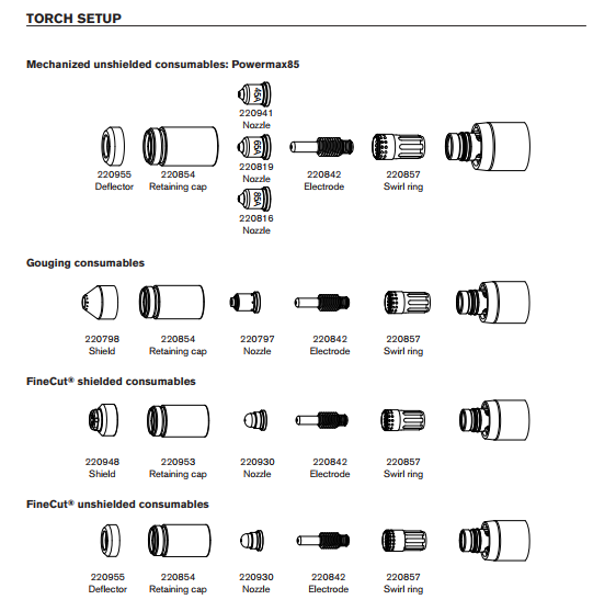
Consumables
The main consumables (for the plasma torch tip) that a member will probably need to buy are:
- Electrode - 220842
- 45A Tip - 220941
- 65A Tip - 220819
- 45A/65A Shield - 220798 (the 220818 drag tip would be used if you were cutting by hand)
- 45A FineCut Tip - 220930
- FineCut Shield - 220948 (the FineCut tip needs a different shield)
You must provide your own electrodes and tips. There is currently a FineCut shield on the plasma cutter, but you may need to provide your own 45A/65A shield.
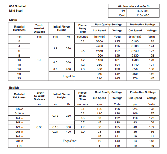
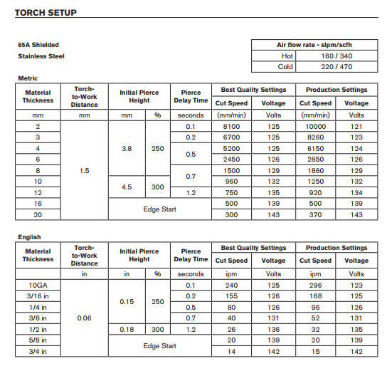
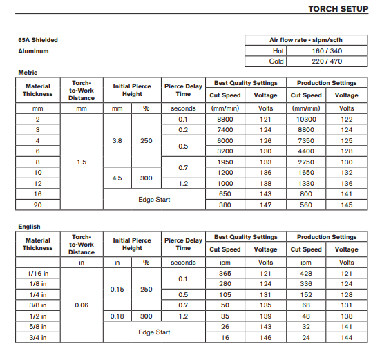
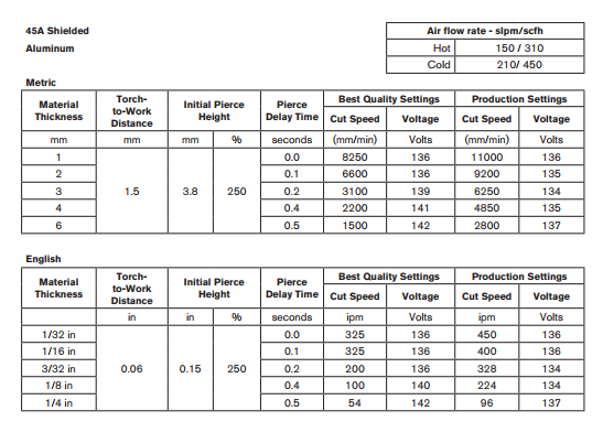
65 Specs
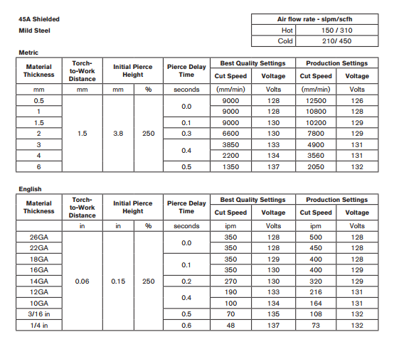
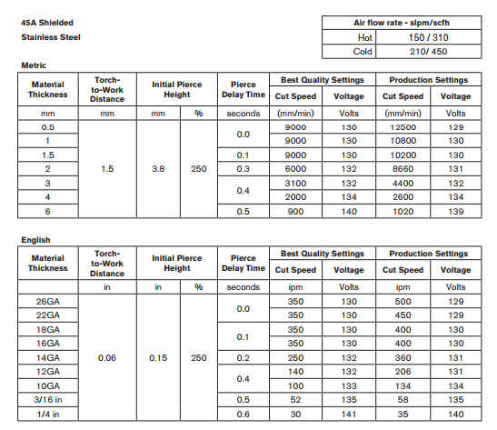
45 Specs
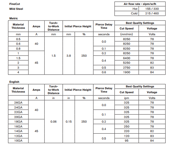
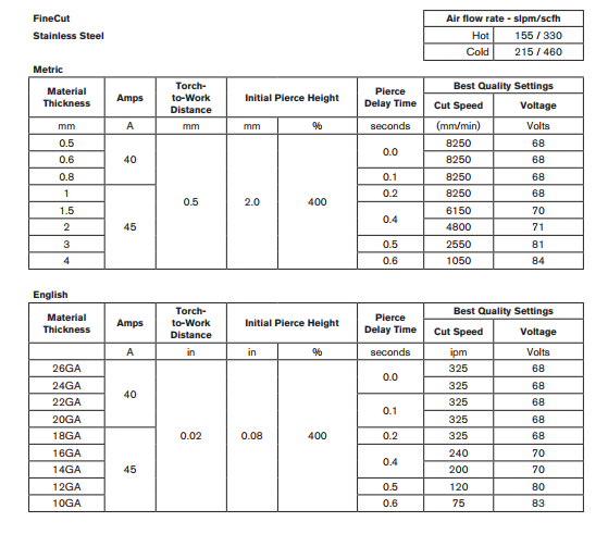
Finecut Specs
Fusion 360
HOW-TO VIDEO: MakeICT Plasma Setup in Fusion 360 (video)
HOW-TO VIDEO: CNC Plasma First Part in Fusion 360 (video)
Fusion 360 can be used to easily generate the G-code for our CNC Plasma Cutter. The following is some useful information that can get you started. To learn more you can check the 2D Profile reference for an explanation of each of the 2D profile settings.
To get started with default settings that work with MakeICT's plasma table, download the following files.
POST PROCESSOR
The first thing you want to do is to grab the Post-Processor. This will ensure that your G-Code matches what our table needs to operate. This really just replaces the M3 with a pierce probe and adds an M5 to stop the torch.
TEMPLATES
You also want to grab the templates for our table. This is not required, but it will save you from having to track down all of the tool settings yourself.
If you do change the tool settings and the dimensions of your cut parts are important, using ‘Compensation Type: In computer’ under the ‘Passes’ tab is recommended for best accuracy. Using ‘Compensation Type: In control’ will cause errors in LinuxCNC without manual editing of the g-code, and will give inconsistent results.
TOOLS
Finally grab the tool files.
Once you have the files all downloaded you will need to upload them to your Fusion 360 account. You only need to do this once, unless the files change and you need to replace them.
Open Fusion 360
- Go to the upper right corner ... you should see your name
- Click on your name and select "Preferences"
- Under "General" ... select "Manufacture"
- Check the "Enable Cloud Libraries" checkbox and click the OK button.
- On the main window, click on the "Show Data Panel" icon in the upper left hand corner (looks like a 3x3 box grid).
- On the left side of the window, you should see a tab that shows "Projects, Libraries, and Samples". If you do not see this, then at the top you should see a big bold < symbol. Click this, and it should take you to the right place.
- Under Libraries click on Assets
- You should now see 4 folders ... CAMMachines, CAMPosts, CAMTemplates, CAMTools
  * CAMPosts - 1 Post Processor File
  * CAMTemplates - 2 Template Files
  * CAMTools - 3 Tool Files
- Click on the folder that you want to upload, and then drag the file(s) from your download folder to the dialog, and click the Upload Button.
- Repeat for each folder. To switch to a new folder, you can either click the < at the top and then click on the Assets folder again. Or, on the far left, you should see the folder you are working on (a triangle symbol followed by > followed by the Folder Name). Click on the triangle, and it will show you all of the folders. If you click on the > symbol, it will give you a drop down with all of the folders.
Now you are ready to begin using Fusion 360 to design your job.
Some basic steps:
Create Sketch
- Start a new Model
- Select the X/Y plane (red/green)
- Create a new sketch
- Insert an image or SVG ... or you can draw your sketch by hand.
- Make sure you have extruded your drawing (especially if you are using an image or SVGlong time). The depth does not matter, it just has to be extruded.
Switch to MANUFACTURE mode
- Add a new setup
- Select "Cutting" operation.
- Click on the bottom left corner of your drawing to select the anchor point.
- Right click on the setup you just created, and select "Create From Template".
- You should have two templates that you added earlier. Use the "MakeICT no leadin or Kerf" for the cases where a quick generation time and getting every pierce is required. The "MakeICT .125 lead in with Kerf" is recommended for dimensional parts but suffer from slower generation time and instability if multiple holes are smaller than .125in.
- You should now have a new tool showing ... it will have a red circle with an exclamation mark. If you don't see this, click the little triangle to the left of the setup.
- Right click on the new tool, and select edit.
- Click on Tool and select the tip size that you will be using for cutting. This should be on the left side under the Cloud section.
- Select the correct material size.
- Switch to Geometry, select the area to cut.
- If you have small parts that may fall into the water, you can add tabs at desired points. Typically you just want one tab per item, to make it easier to remove in the end.
- Click OK to close the edit dialog.
- You should now see the tool path on the drawing. You can right click on the setup to simulate the operation if you want to see how it will cut.
- Final step is to apply the Post-Processor. This will generate the G-Code that you will load on the plasma cutter. Right click on the setup and select Post Process.
- Make sure that the "Configuration Folder" says <My Cloud Posts>. If it doesn't, click the Setup Button, an switch it to Cloud
- You should only have one option, but make sure that the Post Configuration section has the MakeICT plasma processor selected.
- At the bottom Left, change the Units to Inches.
- Change the Output Folder to the location you want to save your G-Code. You will need this on a USB flash drive, to put it on the plasma computer.
Ready to move to the Plasma
Sheetcam
- Open Sheetcam in windows or Linux.
- Click File - New part - Click yes if prompted.
- Choose file you wish to add .svg or .dxf.
- Part should be loaded into Sheetcam.
- Change X & Y coordinates to .15 at the bottom of the screen.
- Click operation - Plasma Cut.
- Choose correct tool & layer.
- Check for lead-ins and lead-in length - Click ok.
- Look at true width by clicking.
- Check starting points.
- Click Edit start points if they need to be modified.
- If everything looks good, click run post processor
- Title accordingly and save as .ngc
LinuxCNC
- Notes: At this time the THC (Torch Height Control) and the Ohmic Touchoff are not wired up. Make sure they are not selected. Will post here when that changes, along with a tutorial on using them.
- Turn on Computer & Table power.
- DO NOT TURN ON PLASMA CUTTER YET!
- Log in to PC
- User Name: plasma
- Password: linuxcnc
- Start LinuxCNC from the icon on the desktop.
- Click "Power" button (top middle of the screen). If the "Power" button is disabled/greyed out, make sure the E-stop is not pressed.
- Click the "Home All" button in the lower right.
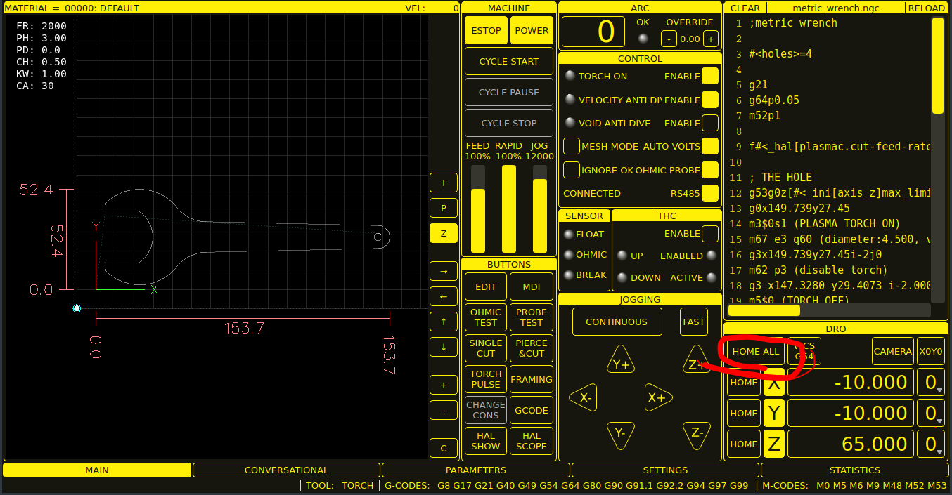
- Move the machine with the arrow keys on the keyboard or with the GUI to the material, and position it according to your Fusion 360 setup file. (e.g. for most files, this is the lower left portion of the material)
- Click "open touch off" button - - Note: only the X and Y need to be touched off.
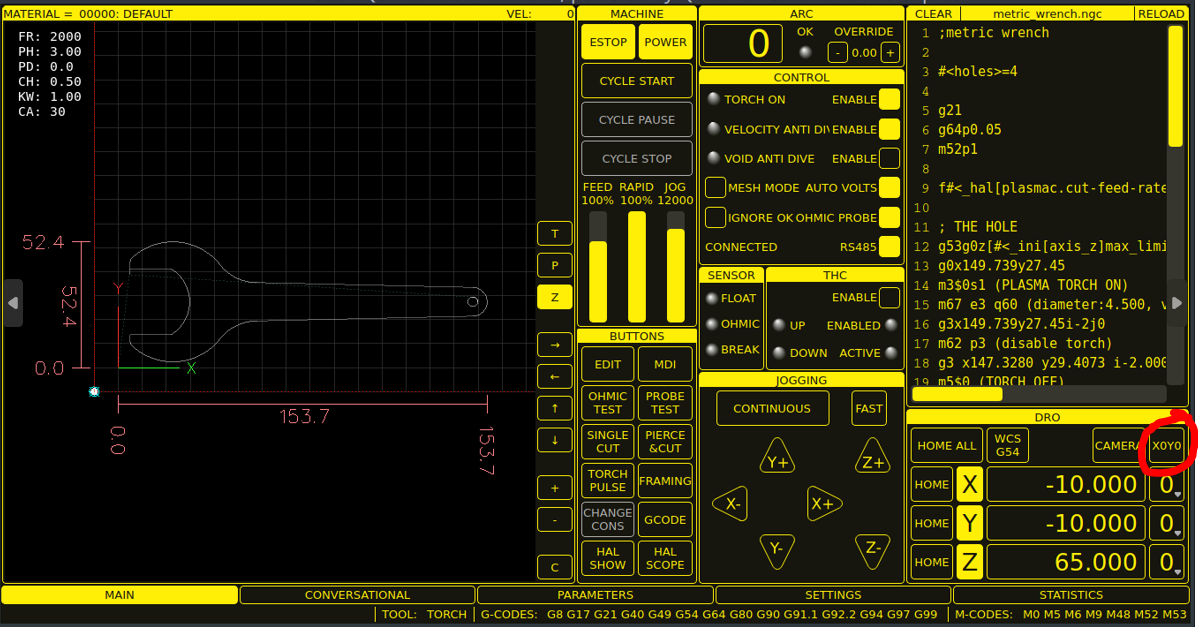
- Click the file button to select your file
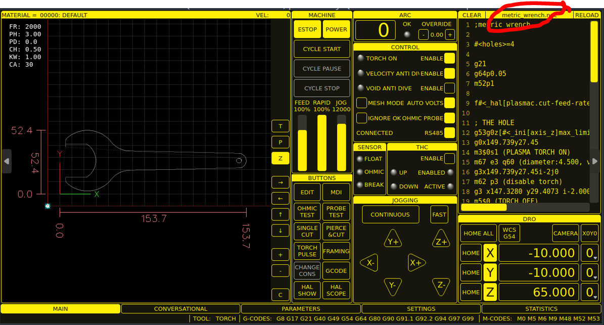
- Choose the correct .ngc file.
- Double check size measurements on screen to material size..
- Dry Run with Torch Off by making sure the torch button is not checked.
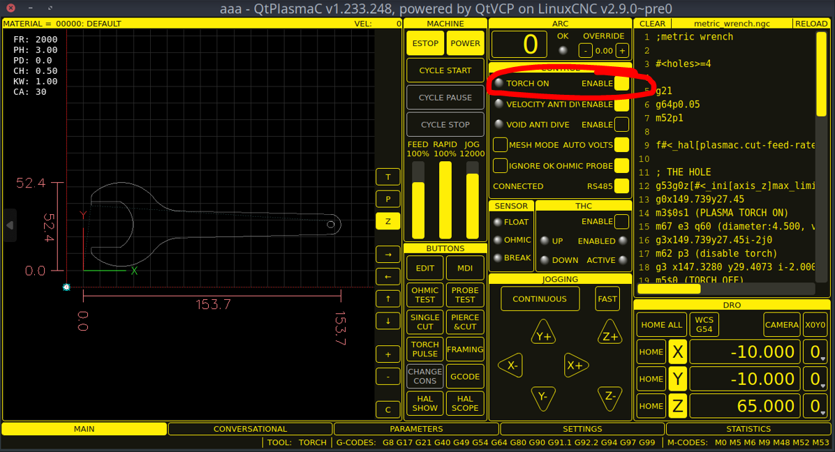
- If everything looks correct, you are ready to test run the program via the Cycle Start button.
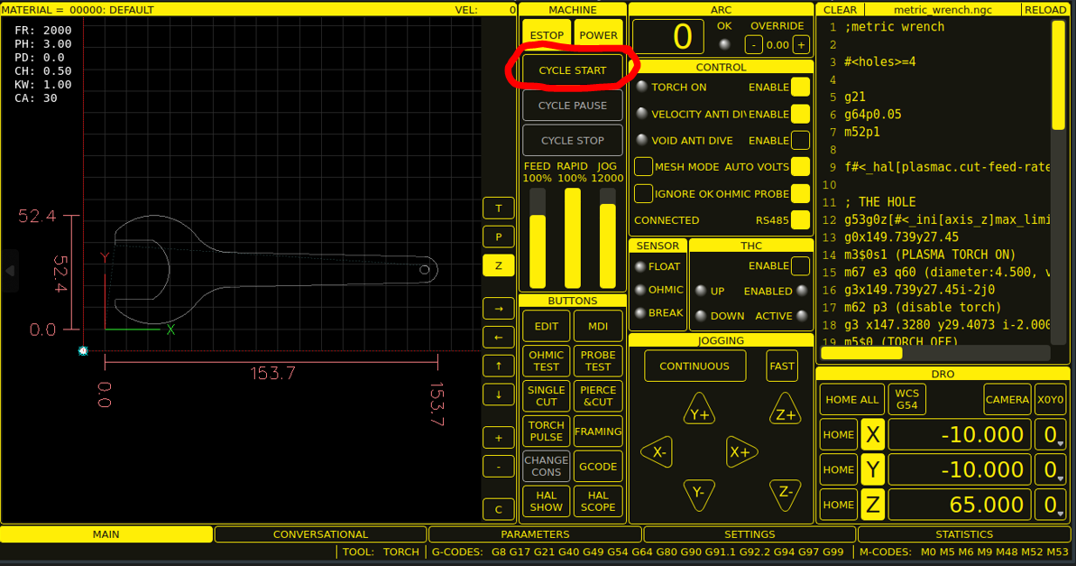
- Press the Cycle Start button and have your hand over the escape key on the keyboard or on the E-Stop.
- If Dry Run goes well you can now turn on the Plasma Cutter via clicking the torch button.
- Set Amperage accordingly on the front of the machine to the nozzle selected and how it was programmed.
- Make sure the compressor is on and the valve is open.
- Before cutting, make sure the welding curtains are closed and everyone has proper eye protection. (Shade 5 or above)
- Treat the torch as if it could turn on at any time.
- Do not put your hand under the torch unless the Plasma Cutter is off.
- You can now press the Cycle Start button while still hovering over the escape key or E-Stop.
- Let the program finish & remove your part or parts.
Clean up
- Use rags to clean off any water that may be on the machine
- Wipe rails and torch shield off with rags.
- Sweep the floor and pick up any trash.
Shutdown
- When finished Shut off the Plasma cutter first!
- Then shut off the table power and shut down the PC.
- Shut off Compressor and clean up any messes you have made.
@TODO (unassigned, no date): Add instructions for setting up sheetcam post processor on personal equipment.
