CNC Plasma Cutter
Consumables
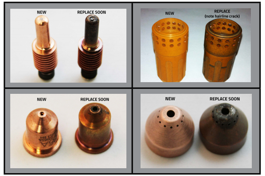
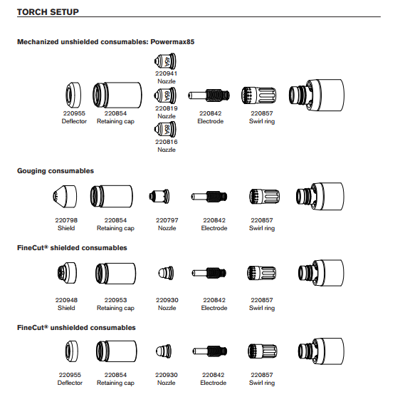
The main consumables a member will need to buy are
- Electrode - 220842
- 45A Tip - 220941
- 65A Tip - 220819
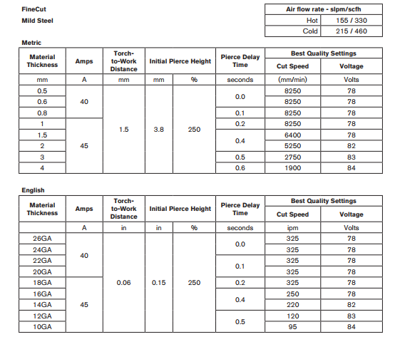
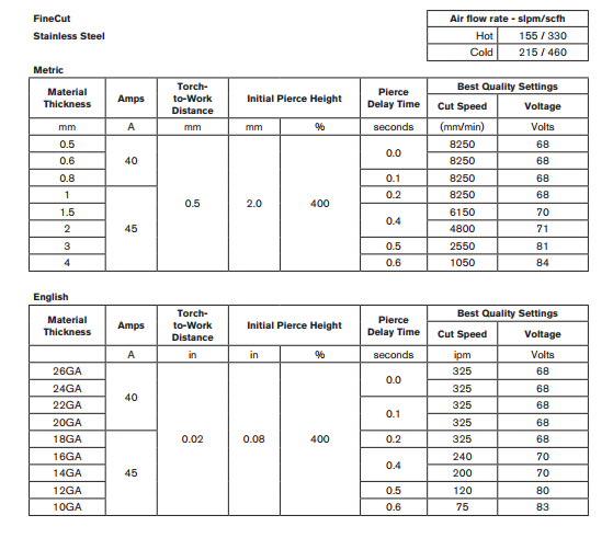
- 45A FineCut Tip - 220930
- FineCut Shield - 220948 (the finecut tip needs a different shield and it is not normally on the plasma)
The rest of the parts are already on the plasma.
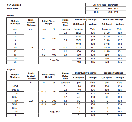
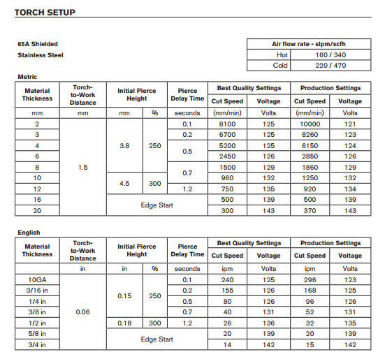
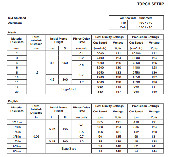
65 Specs
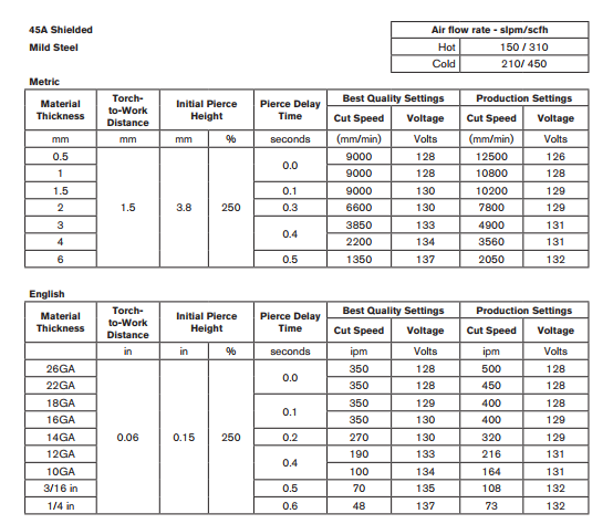
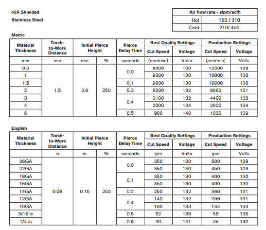
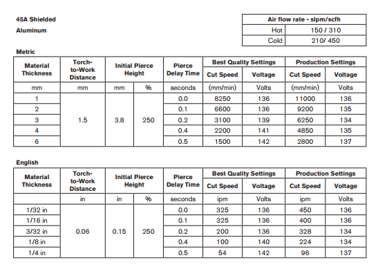
45 Specs
Finecut Specs
Fusion 360
Fusion 360 can be used to easily generate the G-code for our CNC Plasma Cutter. The following is some useful information that can get you started.
Download the following files.
POST PROCESSOR
The first thing you want to do, is to make sure to grab the Post-Processor. This will ensure that your G-Code matches what our table needs to operate. This really just replaces the M3 with a pierce probe and adds an M5 to stop the torch.
TEMPLATES
You also want to grab the templates for our table. This is not required, but it will save you from having to track down all of the tool settings yourself.
TOOLS
Finally grab the tool files.
Once you have the files all downloaded you will need to upload them to your Fusion 360 account. You only need to do this once, unless the files change and you need to replace them.
Open Fusion 360
- Go to the upper right corner ... you should see your name
- Click on your name and select "Preferences"
- Under "General" ... select "Manufacture"
- Check the "Enable Cloud Libraries" checkbox and click the OK button.
- On the main window, click on the "Show Data Panel" icon in the upper right hand corner (looks like a 3x3 box grid).
- On the left side of the window, you should see a tab that shows "Projects, Libraries, and Samples". If you do not see this, then at the top you should see a big bold < symbol. Click this, and it should take you to the right place.
- Under Libraries click on Assets
- You should now see 4 folders ... CAMMachines, CAMPosts, CAMTempletes, CAMTools
  * CAMPosts - 1 Post Processor File
  * CAMTempletes - 2 Template Files
  * CAMTools - 3 Tool Files
- Click on the folder that you want to upload, and then drag the file(s) from your download folder to the dialog, and click the Upload Button.
- Repeat for each folder. To switch to a new folder, you can either click the < at the top and then click on the Assets folder again. Or, on the far left, you should see a the folder you are working on (A triangle symbol followed by > followed by the Folder Name). Click on the triangle, and it will show you all of the folders. If you click on the > symbol, it will give you a drop down with all of the folders.
Now you are ready to begin using Fusion 360 to design your job.
Some basic steps:
Create Sketch
- Start a new Model
- Select the X/Y plane (red/green)
- Create a new sketch
- Insert an image or SVG ... or you can draw you sketch by hand.
- Make sure you have extruded your drawing (especially if you are using an image or svg). The depth does not matter, it just has to be extruded.
Switch to MANUFACTURE mode
- Add a new setup
- Select "Cutting" operation.
- Click on the bottom left corner of your drawing to select the anchor point.
- Right click on the setup you just created, and select "Create From Template".
- You should have two templates that you added earlier. You just have to decide which to use.
- You should now have a new tool showing ... it will have a red circle with an exclamation mark. If you don't see this, click the little triangle to the left of the setup.
- Right click on the new tool, and select edit.
- Click on Tool and select the tip size that you will be using for cutting. This should be on the left side under the Cloud section.
- Select the correct material size.
- Switch to Geometry, select the area to cut.
- If you have small parts that may fall into the water, you can add tabs at desired points. Typically you just want one tab per item, to make it easier to remove in the end.
- Click OK to close the edit dialog.
- You should now see the tool path on the drawing. You can right click on the setup to simulate the operation if you want to see how it will cut.
- Final step is to apply the Post-Processor. This will generate the G-Code that you will load on the plasma cutter. Right click on the setup and select Post Process.
- Make sure that the "Configuration Folder" says <My Cloud Posts>. If it doesn't, click the Setup Button, an switch it to Cloud
- You should only have one option, but make sure that the Post Configuration section has the MakeICT plasma processor selected.
- At the bottom Left, change the Units to Inches.
- Change the Output Folder to the location you want to save your G-Code. You will need this on a USB flash drive, to put it on the plasma computer.
Ready to move to the Plasma
