Breadboards
Breadboards, or Solderless Breadboards, are a commonly used tool for prototyping electronics, there are some common assumptions made about them, that people generally take for granted, once they know.
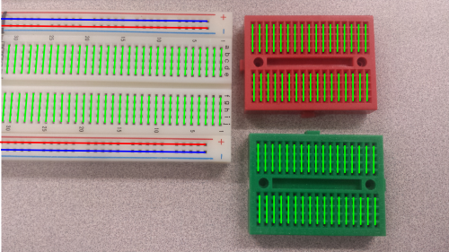
The first of them is how the breadboards are connected. Each breadboard has a series of rows, often labeled with numbers, and columns, often labeled with letters. (If you call them rows, or columns, it doesn't matter.) Each row, is connected together. They have basically springs so that a wire put into the row, connects to all of them. Two line that run along the sides, are for power.
Here's an example, of how they are connected overlaying a picture of a board, where all of the green lines are individual connections. The Blue lines are intended for Ground, GND, or Negative, and the Red for Vcc, Positive. Note that you can use multiple voltages, but generally all grounds lines should be tied together. (Thought there are specific scenarios when they shouldn't be.)
